Alright, there is some progress on the front of my 68040 to 68060 adapters. In the last month I have made a serious improvement of my lab: a simul focal microscope with double boom stand.
This has vastly improved my ability to see what I am actually soldering, instead of almost flying blind.
This led me to attempt another approach to making 68060 adapters, this time I could maybe be less of a butcher with a soldering iron. And with so much visibility, it makes sense to learn from the others out there. Adam Polkosnik has perfected his way of making 060 adapters and was kind enough to teach me all of his secret tricks, some of which I will document here.
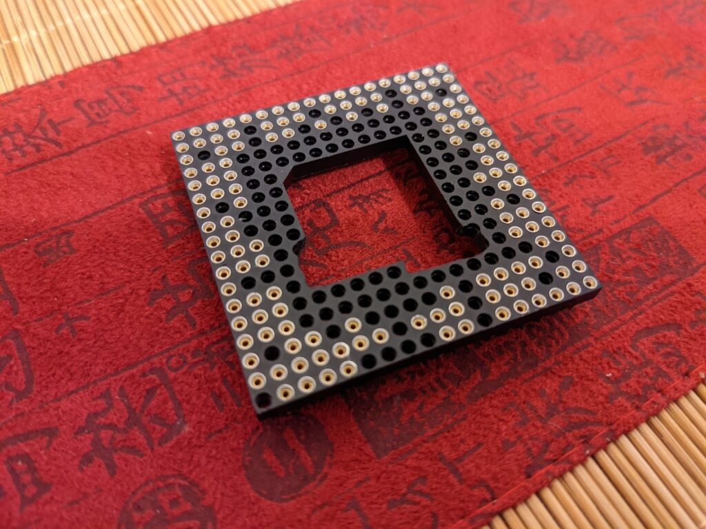
My favorite of these tricks is to use actual PGA sockets instead of cutting 400 single pins out of pin headers. The original 68060 adapter instructions suggested to cut the VCC pins between the upper and lower PCB. A smarter and cleaner way that I learned from Adam, is to use a third PGA socket to keep the distance and separate the 5V and 3.3V circuits safely. This gets rid of a very destructive part of the construction of these adapters.
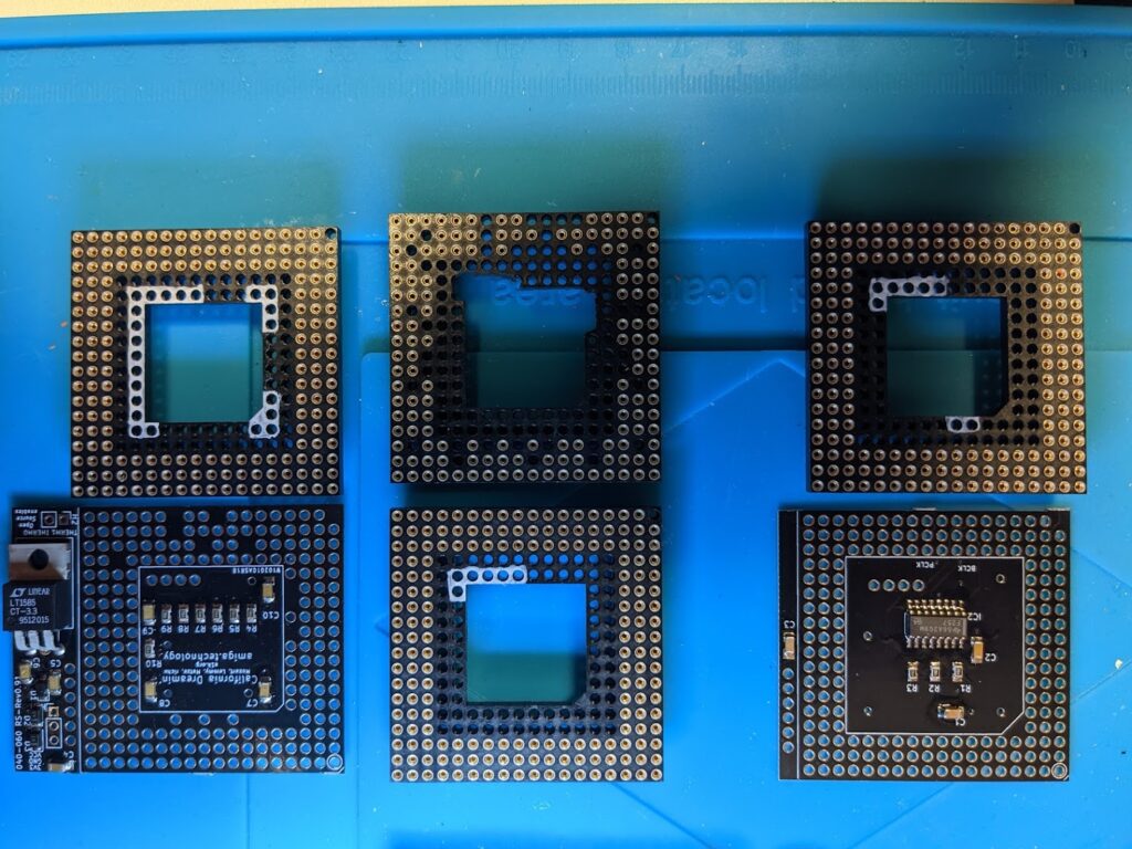
The PGA sockets I found on eBay have five rows on substrate, even though they only come equipped with three rows of pins for the 179 pins of the 68040 processor. Unfortunately the PCB design placed a few parts under the inner, unused rings of the socket. But a little action with my dremel can solve this problem easily.
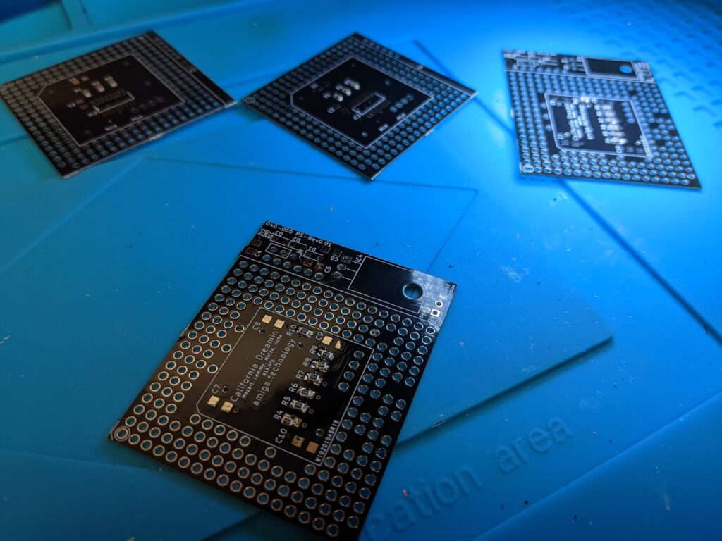
And because switching between tasks is expensive, I decided to make two of these adapters at once. Great practice, but not too smart as I will learn later. A few hours, spread over a couple of evenings later, and I had all the parts together for the big test.
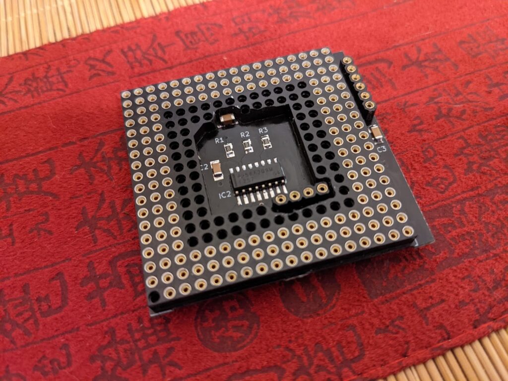
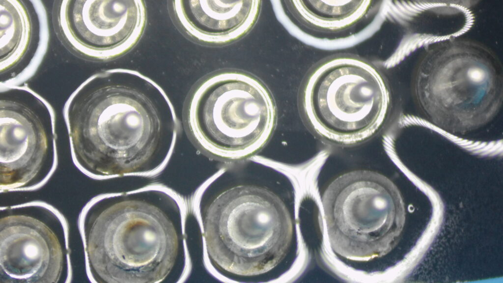
Check out how nice and clean these look
My Dremel game is far from perfect, but it does the job.
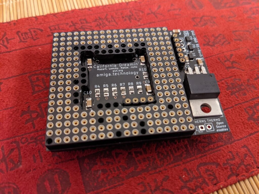
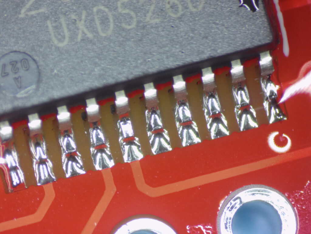
The big test.. and … NOTHING. What a disappointment. Double checking the solder joints, everything seems to look clean and rigid. So let’s look at the adapter in KiCAD and measure with my multi meter.
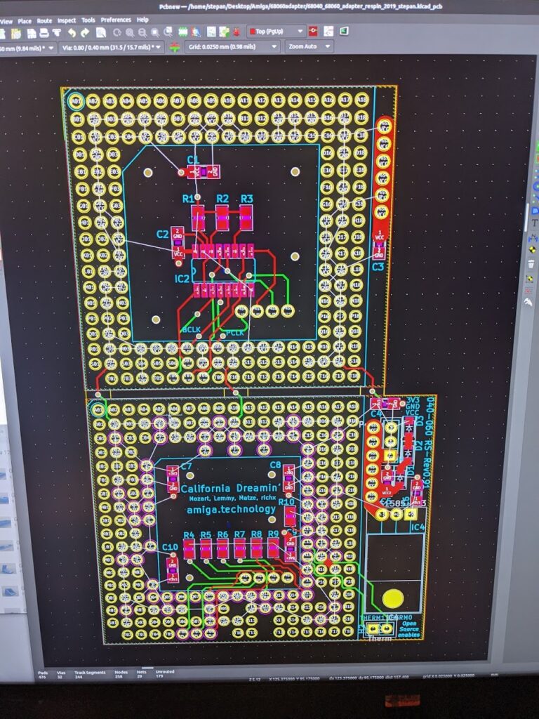
The solid row of six pins on the side carry VCC between the two PCBs, which is routed through the LM1585 regulator. But there is no measurable voltage on those pins. What’s going on? Let’s analyze continuity between what’s coming in from the 68040 socket and those pins. NOTHING! AGAIN?! How about GND? Nothing, either!? Something fishy is going on. Where’s my GND? I have the sudden feeling that John Hertell’s wraith will come my way!
Did PCBway mess up my PCBs? The only adapter that I could get working, came from OSHpark. But since 3 OSHpark adapters cost 8 times of what 10 PCBway adapters cost, I had chosen to go with a different PCB manufacturer this time. What was different?
So,… One thing that was different, was that OSHpark accepts kicad_pcb files. PCBway wants you to upload Gerber files. Did I mess up the Gerber export?
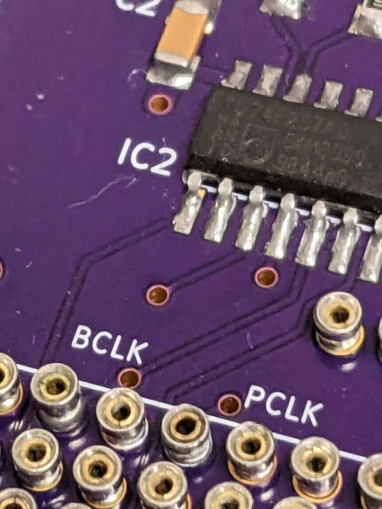
OSHpark PCB 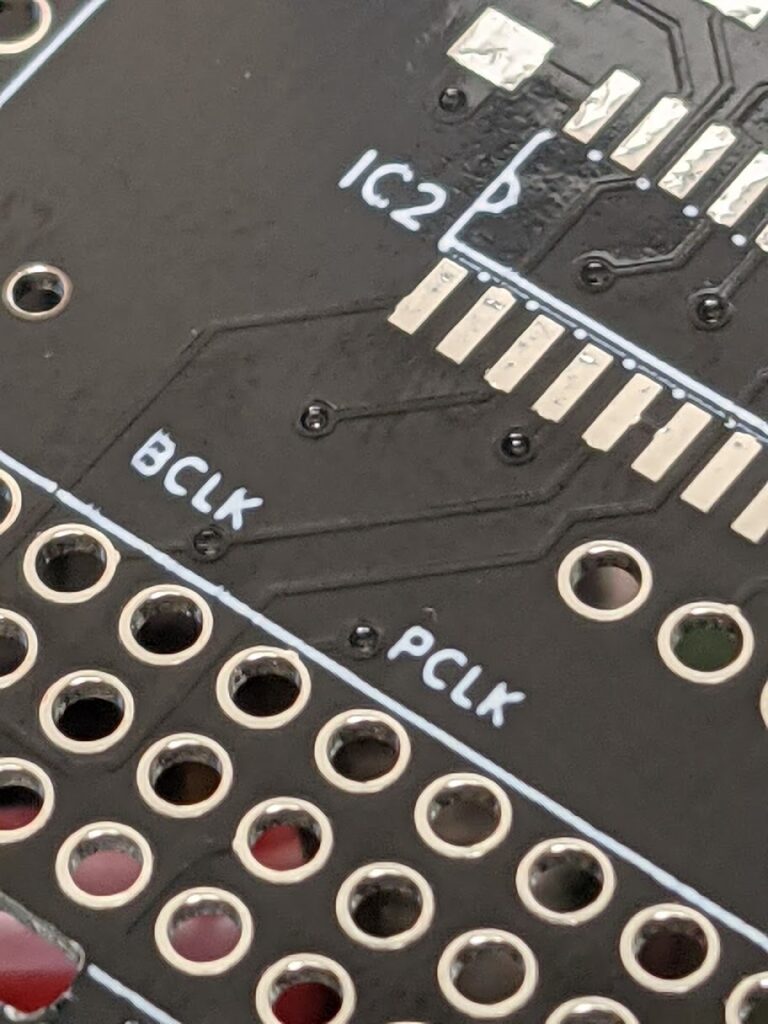
PCBway PCB
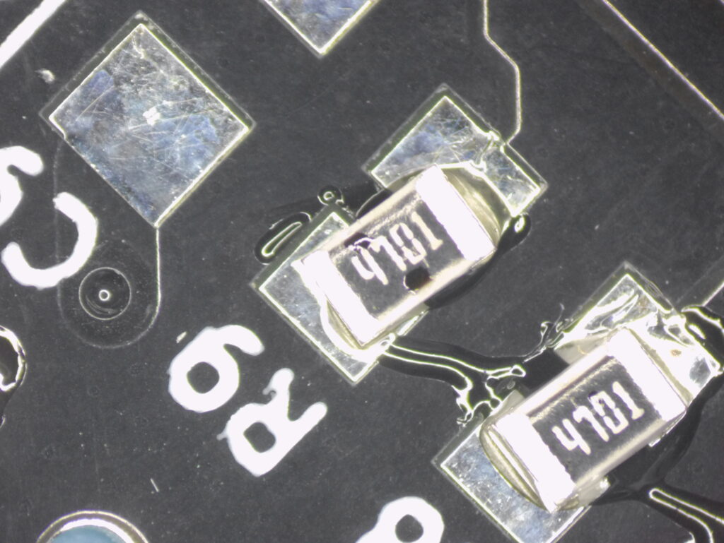
WHOOPS! Something is missing around those traces. It turns out that the source files had outdated fill zones and apparently I never updated them before my Gerber-Out. Someone hand me a brown paper bag. That’s an absolute rookie mistake right there. And it took me three non-working adapters before I figured it out, too. Fool me, once, twice, … nevermind.
So the future will bring new PCBs and another attempt. Together with my new microscope I am pretty sure I will master a few more of these adapters soon.
Meanwhile, we finally got bikes last month and took a trip up to the city!

Stay warm, if you are suffering the cold of this winter in these weeks, and be safe.

The first cherry blossom trees are blooming 
Spring is around the corner
So long, and come back to read my update soon!
Hi Stefan,
can you share details about the microscope model?
I’m currently looking for something similar.
Thanks a lot.
Eduardo
Eduardo, apologies for the long delay. I bought this on AliExpress from a vendor called amszoom (yeah, lol!). At the time of writing they have it here: https://www.aliexpress.com/item/4000525909395.html