
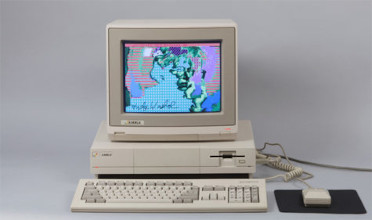
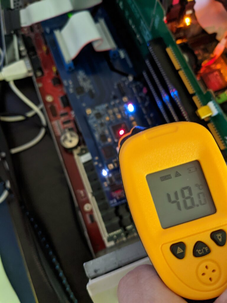
A few days ago I did some temperature measurements with my zz9000 graphics card from MNT GmbH in Germany, which turned out to be surprisingly hot. It started out as a test of the CPU temperature of my freshly overclocked MC68060RC50 (rev6) running at 100MHz, when I noticed that the graphics card seemed to run hotter than the CPU.
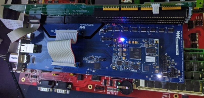
Particularly the FPGA and the two capacitors C154 and C155 were transforming a lot of electricity into hot air.
One day later, after installing Linux/m68k from scratch over night, the Amiga 4000 didn’t boot anymore. Of course I thought that I killed the CPU. 100% overclocking can’t be good, right?
I switched Kickstart chips, as Guillaume suggested, and the machine booted again. That was my initial observation. But what really fixed it was taking out the daughter board. That’s odd. Because while the card was hot (particularly some capacitors next to the FPGA), it wasn’t electrical death kind of hot. Or so I thought.
But since Lukas Hartmann of MNT fame had mentioned a few boards in the field having heat issues, he helped me debug my board and it turns out that all power rails on the FPGA board were ruined.
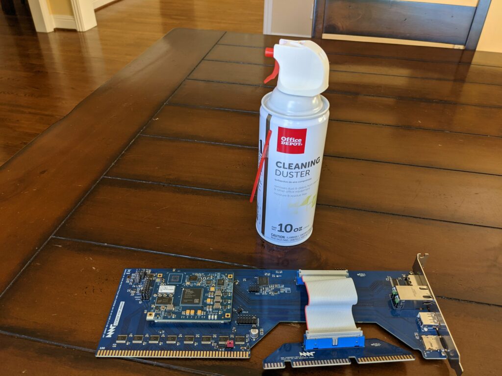
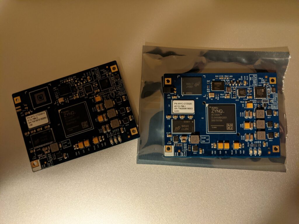
Only one way to get the Amiga back to life: exchange the FPGA board on the zz9000. Mouser sells the modules from MYIR. To be on the safer side, I ordered the version with industrial temperature range instead of the commercial one for an extra 20 bucks. The product number is MYC-C7Z020-4E1D-766-I. You never know how hot it’s gonna get in that case with all the projects that have not yet been realized.
Meanwhile i also ordered a heat sink for the FPGA which is still on it’s way. But all these measures are of course not really solving the problem of why the card died in the first place. Here I want to send big kudos to Lukas Hartmann for a timely analysis including a simple fix.
The fix exists in two variants. The original fix requires you to drill a hole into the PCB or the carrier board, right next to one of the level shifters because the trace we want to interrupt is on one of the inner layers of the PCB. Alternatively it is also possible, however, to cut the trace right between the socket and the via that’s taking the trace “underground”.
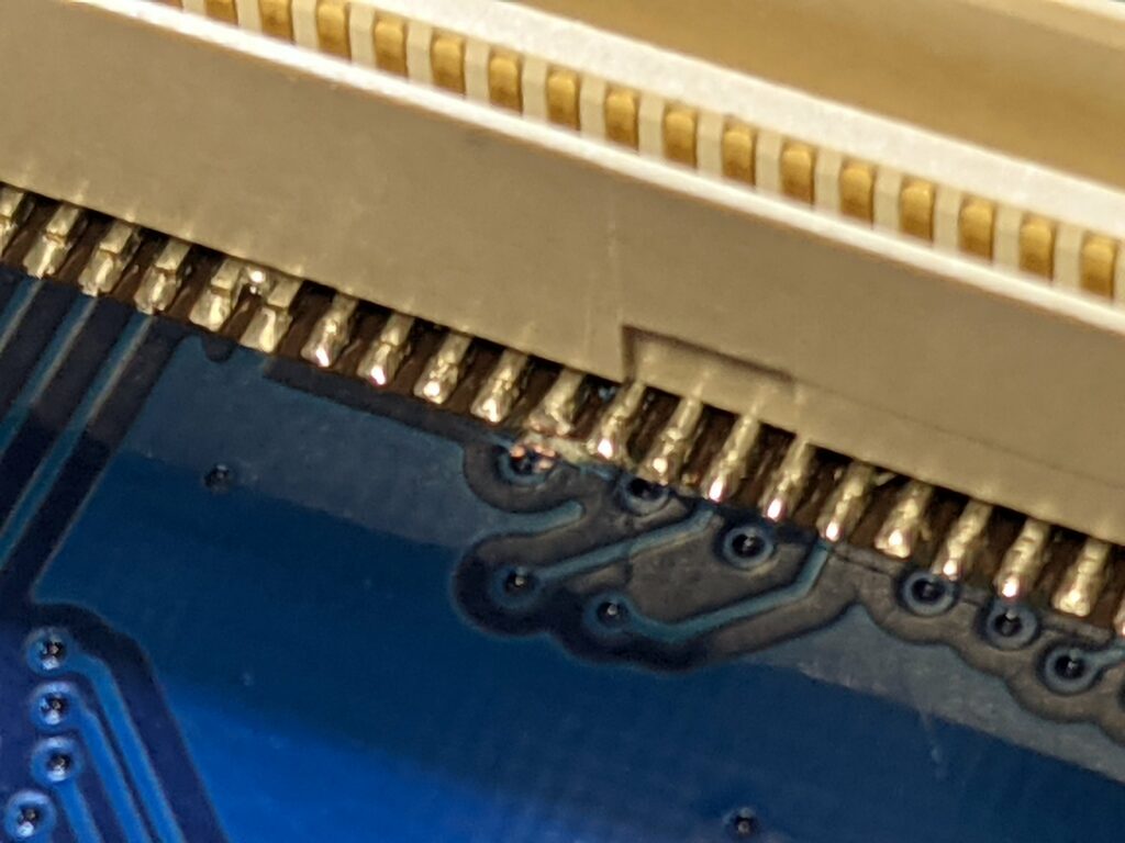
This will sever the 3.3V that were bleeding into the 1.8V on the FPGA board. The multimeter confirms we are no longer connected, et voila! The card is successfully reworked.
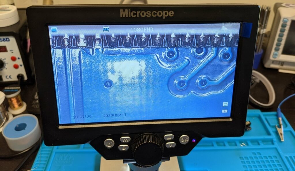
The microscope was definitely helpful when cutting the trace, particularly because cutting around on such fine hardware makes me very nervous. I used a cheap scalpel from Amazon that came with 10 blades, so I might never run out.
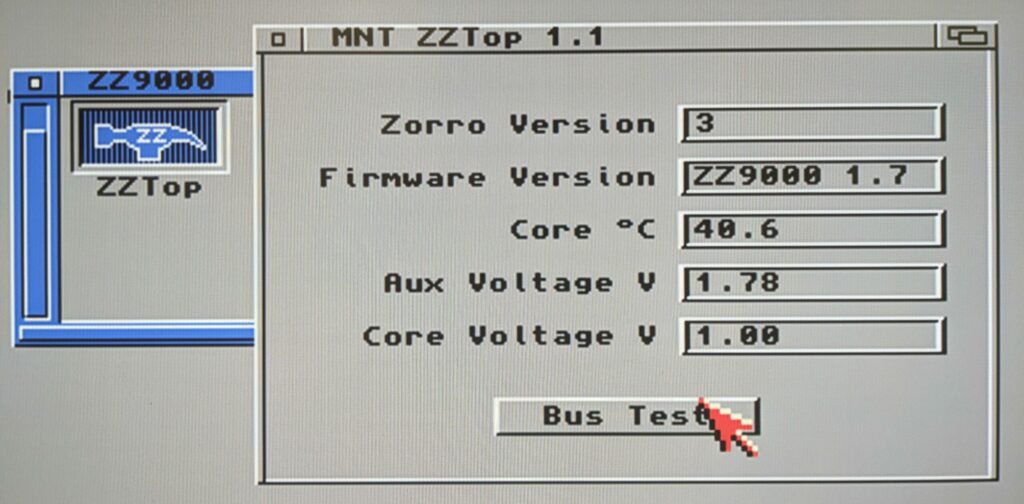
The FPGA die temperature is a lot lower after this change. Even after an hour or two of operation the die temperature is not raising above 60 degrees Celsius anymore. With the latest version of the zztop utility you can also see the AUX voltage is now at around 1.8V as expected.
The die temperature measured by the awesome zztop utility (I was hoping this would come to exist) is a few degrees higher than the surface temperature that I can measure. I guess that is expected, but good to keep in mind.
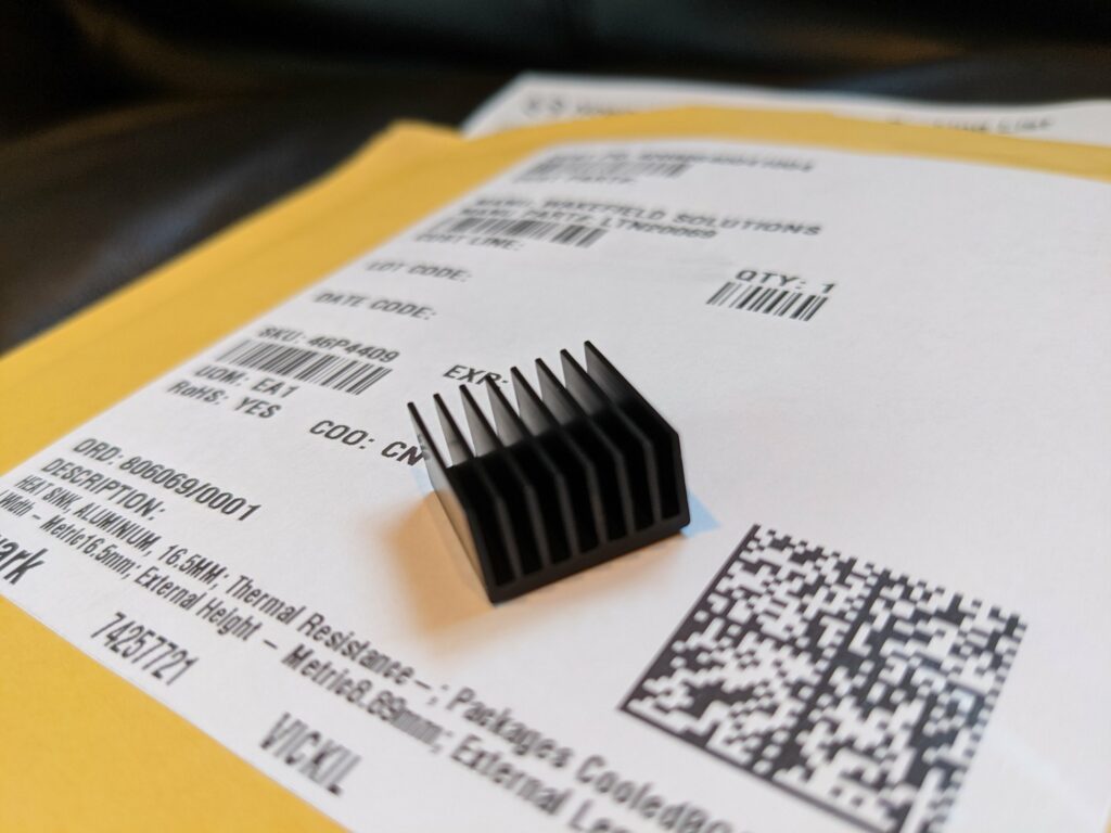
Funny enough, the mailman brought the Wakefield LTN20069 heatsink right while I was doing my temperature tests.
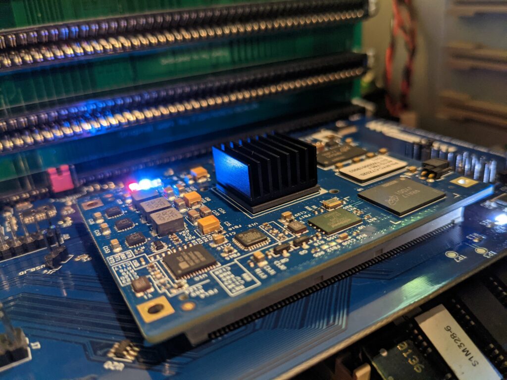
And right away, the heatsink cuts another 5 degrees Celsius (9F) out. Pretty awesome.
Now folks, if you’re in the Bay Area and don’t want to do this rework yourself, you can drop the card off with me in Mountain View and I can apply the fix for you. It only takes a few minutes.